

LVDS drivers (and LVDS receivers) can be the source of significant interference emissions. Disturbances that are caused by the LVDS drivers may penetrate to the outside through the defective shielding of cables and connectors and thus lead to emissions.Unwanted common-mode currents of the LVDS drivers are mostly responsible for these interference emissions. The common-mode currents largely depend on the type of LVDS module. Practice has shown that LVDS receivers too can output significant common-mode currents into the LVDS lines. The transmission system connectors are not usually able to withstand common-mode currents as well as differential-mode currents. Symmetrical transmission systems couple out much more common-mode currents. Differential-mode currents cancel each other out due to the fact that the transmission system is symmetrical and are thus suppressed. If the connectors' symmetrical lines are not symmetrical in relation to the shielding, additional differential mode currents couple out from the connector.Measurement technology may help clarify the common-mode current problem and enable the integration of expedient interference suppression measures in the right place.
High-resolution measurements have to be performed on the drivers' and receivers' LVDS pins. The MFA-R 0.2-6 near-field probe achieves the required resolution
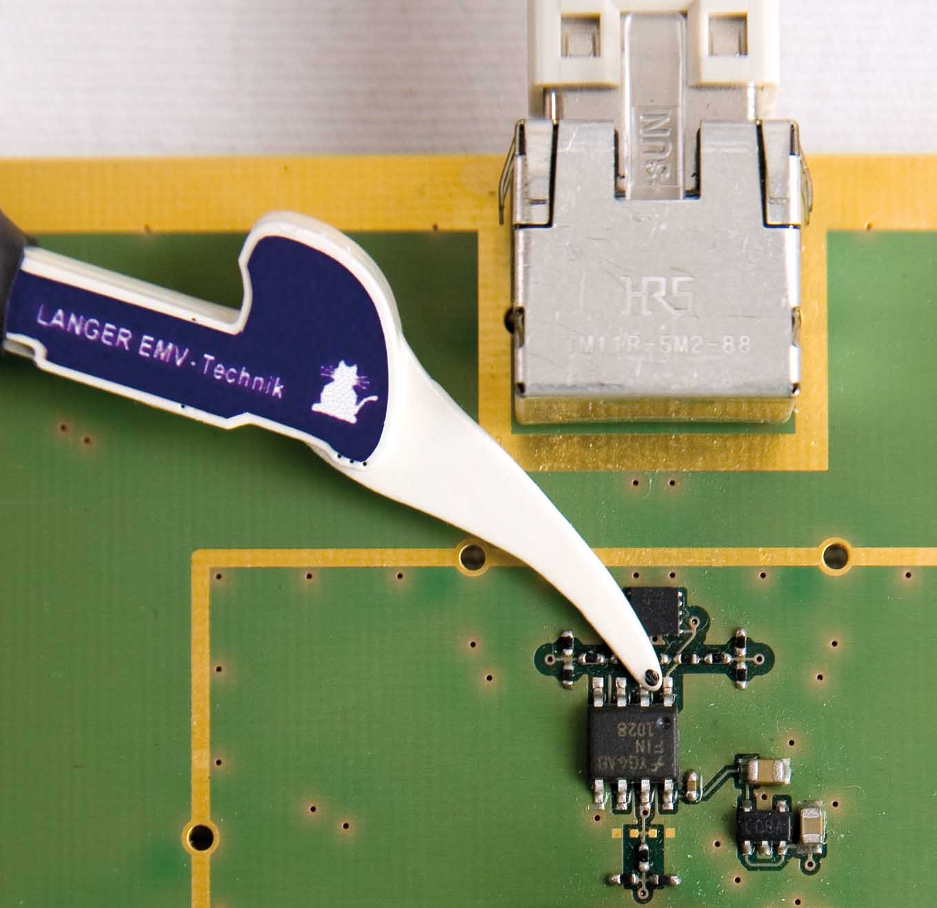
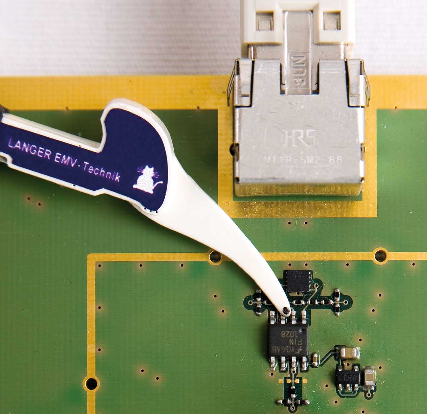
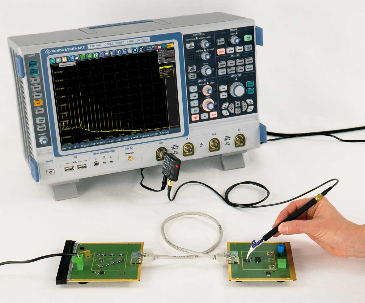
Figure 1 shows the measurement set-up. The LVDS modules are connected via RJ-45 sockets and patch cables. The MFA-R 0.2-6 near-field probe is used to carry out the measurements on the pins according to Figure 2 and 3.
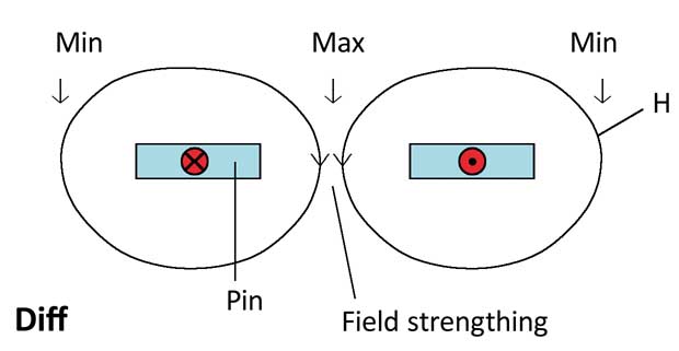
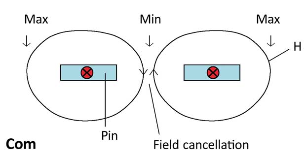
The fields between the pins are added together if the LVDS pair carries differential-mode current (Figure 4). The intensity of the magnetic field between the pins is higher than that outside the pin pair. The magnetic field of the common-mode currents between the pins is cancelled if the LVDS pairs carry common-mode current (Figure 5). This means that only a low field intensity is measured between the pins of the LVDS pair while the field intensity that is measured outside the LVDS pair is higher.
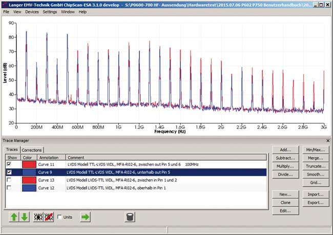
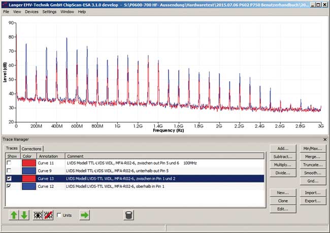
Two measurement places that are relevant for clarification with the MFA-R 0.2-6 near-field probe can be defined on the basis of these relationships. The probe's coil surface has to be placed between the LVDS pin pair on the one hand (Figure 2) and alongside the LVDS pin pair on the other (Figure 3). Figure 6 and Figure 7 show the measurement results. The red curve shows the measurement between the LVDS pin pairs (Figure 2). The blue curve shows the measurement outside the LVDS pin pairs (Figure 3).
The measurements were carried out with the ChipScan-ESA measurement and documentation software. The measurement results indicate whether differential-mode or common-mode current is present.
The pins of the TTL-LVDS driver's output pair (Figure 6) carry a current with a predominant differential-mode share. The maximum field intensity is measured between pins 5 and 6 while the minimum value is obtained in the measurement alongside the pins (Figure 4). The small difference between the fields indicates that an additional common-mode current share is present.
The input pair of the LVDS-TTL receiver (pin 1 and 2) is measured in the same way. The measurement result shows that the field intensity between the pins is lower than that alongside the pins (Figure 7). This means that the common-mode current is generated by the receiver (Figure 5).
The common-mode currents of the LVDS-TTL driver and TTL-LVDS receiver would couple out disturbances via the RJ-45 connector and emissions via the patch cable. This is prevented in this case by a data line choke integrated at the output of the TTL-LVDS driver, pins 5 and 6, and the input of the LVDS-TTL receiver, pins 1 and 2.
It initially seems strange that the input of the LVDS-TTL receiver should output a common-mode current, a behaviour that is not usually expected. If the common-mode currents had not been examined, nobody would have hit on the idea of installing a data line choke at the input pins.The output of common-mode current from the LVDS inputs depends on the type of the LVDS module. The LVDS driver may also output common-mode current. This means that the current output from the pin pair, common-mode or differential-mode, depends on the modules' inner wiring and is not foreseeable by the IC user. Without clarification through a measurement with a MFA-R 0.2-6 near-field probe, it is not possible to detect this relationship and implement efficient interference suppression measures.