Introduction
When measuring ESD processes in electronic systems, there is a risk of the measuring device (oscilloscope) being destroyed or the measurement being influenced by interference fields and interference currents from the ESD gun.
The ESD gun can introduce conducted interference via the measurement inputs, the power supply or interface inputs in the device. Furthermore, the fields emitted by the housing of the ESD gun can be coupled into the measuring device. The conducted or field-bound interference processes that penetrate the oscilloscope can be so high that the measuring device is damaged or destroyed.
The ESD gun can also significantly interfere with the recording of the measurement process. The measurement result can be completely altered so that the measurement does not contain any useful information. Measuring the processes in the electronic device (DUT) can become almost impossible.

Set-up
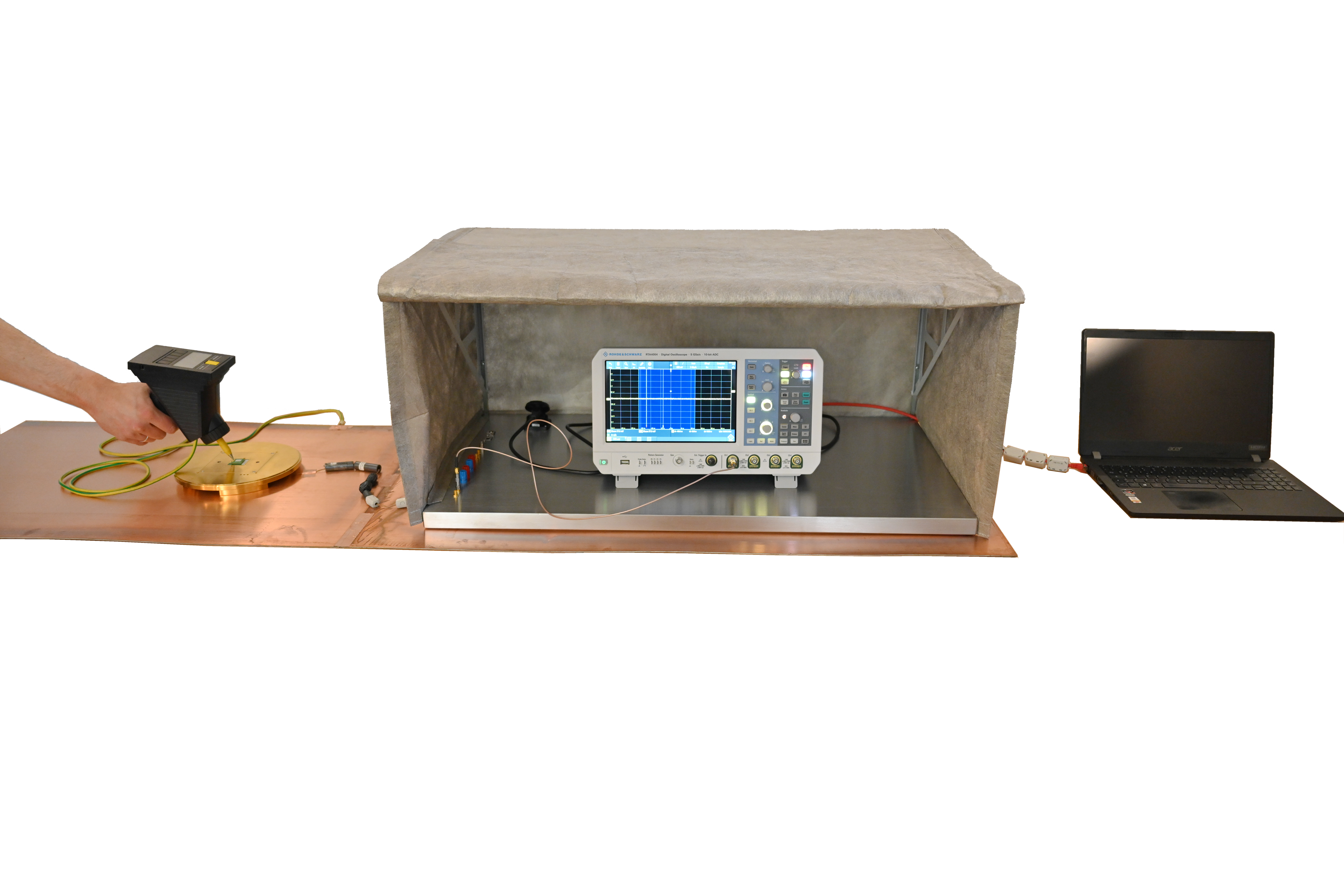
The measurement inputs are routed on the ground plate of the shielding tent via solid metal shielded feedthroughs (SMA connectors) into the interior of the shielding tent. The electronic assembly to be tested will contain a system for measuring the ESD processes. This measuring system could measure the current, voltage, electric field, or magnetic field of the ESD process (e.g. EPM 02 dE/dt Field Meter, BPM 02 dB/dt Field Meter, SM 02-1 Shunt 1 Ω from Langer EMV‑Technik GmbH).
These measuring systems must limit their measurement to the physical quantities to be measured and must not allow any further coupling. They must be extremely well shielded. The measuring systems must be connected to the measurement input of the shielded tent using RF cables with solid metal shielding (semi‑rigid). Cable shields made of braided shielding are unsuitable. In the shielded tent, the connection to the oscilloscope inputs can be made with double‑shielded cables.
The oscilloscope's power supply is routed to the outside via a mains filter integrated in the ground plate of the shielding tent. The interface connections of the oscilloscope to a PC or laptop are routed opposite the ESD side of the shielding tent (on the right‑hand side) through the magnetic closure of the shielding tent. Inside and outside the shielding tent, these cables must be fitted with several ferrites (hinged ferrite) to block the interference. The laptop is positioned directly to the right of the shielding tent (not necessarily on the common metal plate; this must be tested when the measuring station is commissioned). The interface cable of the oscilloscope is connected to the laptop. The laptop's power supply is routed via several ferrites.
If ESD processes are generated, the shielding tent must be closed, and the oscilloscope can no longer be operated directly. The oscilloscope is therefore remote‑controlled via the laptop. If the shielding tent is closed for a longer period, the oscilloscope can become unacceptably hot. To prevent this, a fan insert can be placed behind the shielding tent, which draws air through the shielding tent and thus cools the inside of the shielding tent. This is an advantage over solid shielding.
The permissible voltage at 50 Ω oscilloscope inputs is approx. 5 V. Output voltages in the range of 1000 V can functionally occur at the outputs of the measuring system during ESD processes. If no appropriate attenuators are connected upstream, the oscilloscope input can be destroyed. Attenuators with sufficient attenuation values must be used. Attenuators with values of up to 50 dB attenuation may be required. It is advisable to start the ESD measurements with a very low ESD voltage value to see whether the attenuators are correctly dimensioned.
Product reference
MP ESD Generator Calibration set
The MP ESD Generator Calibration set is used to measure the waveform of the discharge current of an ESD generator. In addition, transient processes in the waveform of the discharge current can be measured and visualized in the frequency range up to 3 GHz. These transient processes influence the test result when testing devices. Variations between different types of ESD generators can be attributed to this, among other things.
To obtain a reproducible test result, it is advisable to regularly check the waveform of the discharge current generated by the ESD generator and defined by the IEC 61000‑4‑2 standard. The mobile measuring station fits on a developer’s workstation and can be set up and dismantled quickly. The MP ESD Generator Calibration set is also available with a larger working area of (900 × 500 × 650) mm.

