Fields of application
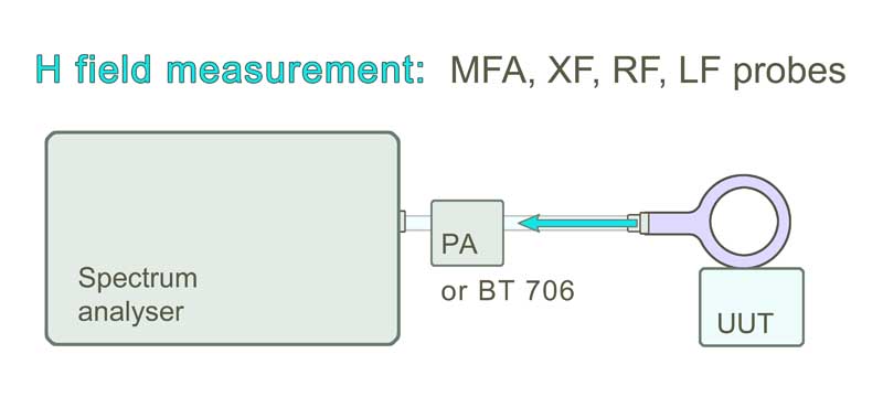
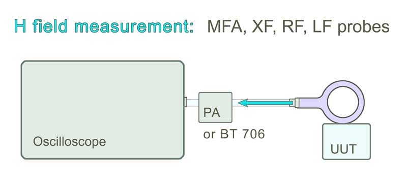
RF field measurement for E- and H-field with near-field probes and a spectrum analyzer or an oscilloscope.
Correcting Characteristic Curves of Magnetic Field Probes
RF-type probes from Langer EMV-Technik GmbH
Magnetic field strength and current determination
The following paragraph explains how magnetic field strength and underlying currents are calculated from the results of near-field measurements.
A magnetic field probe emits a Uprobe voltage signal output which is dispersed into a spectrum by a spectrum analyzer. A correction factor KH is defined which describes the relationship between the voltage signal and the associated magnetic field HRF. The magnetic field HRF is linked with a current IRF. Another correction factor can, thus, be defined based on the current IRF.
Magnetic field correction:
The magnetic field strength HRF in the coil of the magnetic field probe can be calculated from the voltage output signal of the Uprobe magnetic field probe by means of the correction characteristic. The correction factor of the magnetic field probe is independent of the measurement geometry in each individual application, i.e. the probe can be guided at an arbitrary distance and angle relative to the electric conductor without any correction error (Figure 2). The result is the average magnetic field that is enclosed by the probe coil (Figure 1).
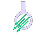
Figure 1 Field strength distribution in the probe coil
Use of the correction factor KH in the adapted quantity equation:

Example of how the quantity equation is used, Figure 3:
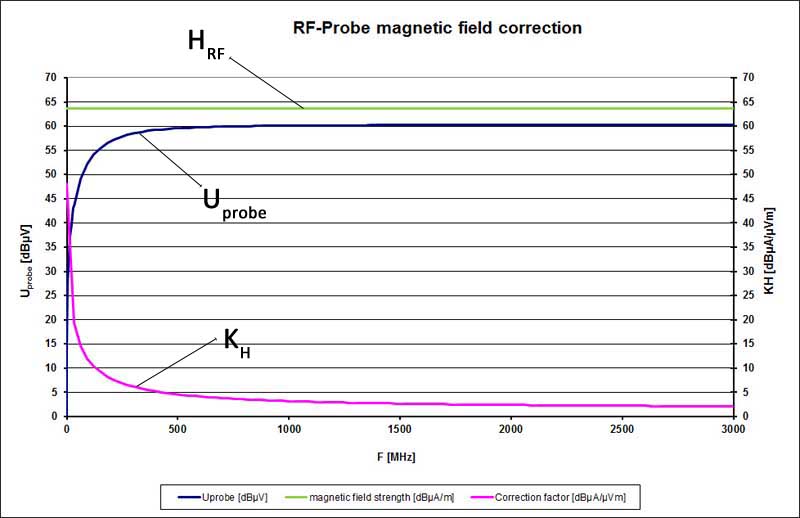
In Figure 3 the magnetic field probe was located in a magnetic field that is constant over the frequency range. Due to the coupling factor the voltage which is induced in the probe depends on the frequency. The coupling factor intermediates between the measured voltage Uprobe and the mean magnetic field strength. The existing magnetic field strength is obtained if the correction factor is added to the measured voltage Uprobe (logarithmized quantity equation).
The mean magnetic field strength HRF can be determined from the measured curve Uprobe and the correction characteristic KH using the quantity equation. The result is shown in Figure 3.
Current correction:
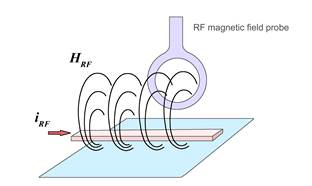
There is a consistent physical correlation between the magnetic field HRF and the current IRF which depends on the geometry of the current conductor layout. The given correction factor KI thus refers to a defined reference set-up.
The determined current values Icorr are only correct if the geometric parameters coincide with the reference set-up when the probes are used. If there are deviations from this set-up, the current values Icorr will also deviate. The calculated current value Icorr can only be used as an orientation value.
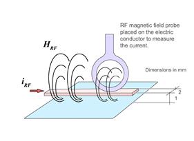
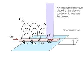
The reference set-up has the following geometric parameters (Figures 4 and 5):
- Width of the conductor run 2 mm
- Height of the conductor run above the ground system 1 mm
- Probe placed on the conductor run
Use of the correction factor KI in the adapted quantity equation:

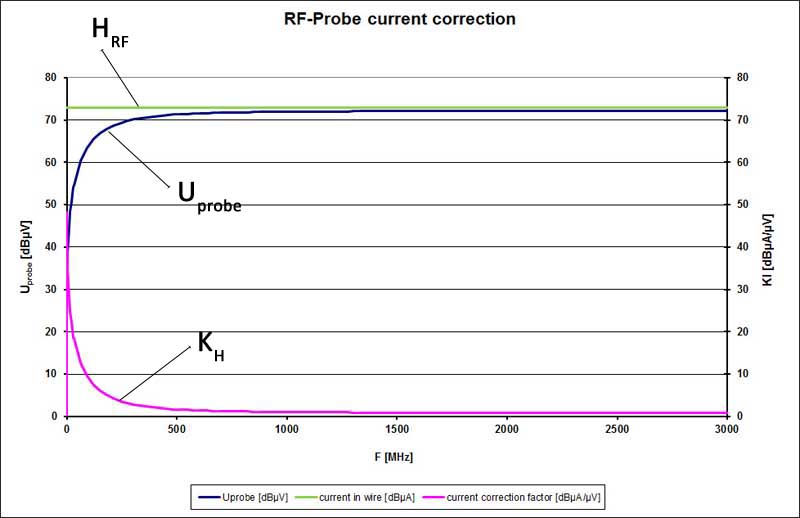
The example is based on a current that is constant over the frequency range (Figure 6). This current induces a voltage in the magnetic field probe which is measured as Uprobe by the spectrum analyzer. The frequency-dependent correction factor is added (logarithmically) from the voltage waveform to obtain the current in the conductor. Icorr is the current in dBµA which flows in the reference set-up.
Download Correction Characteristics
You can download the correction data for our special magnetic field probe types as xlsx-file.
- LF probes
- RF probes
- RF E-field probes
- XF probes
- XF E-field probes
- SX probes
- SX-E 03 probe
- MFA probes
Downloads
Quality features of Langer near-field probesOverview all near-field probes Langer EMV-Technik GmbH

