

Introduction
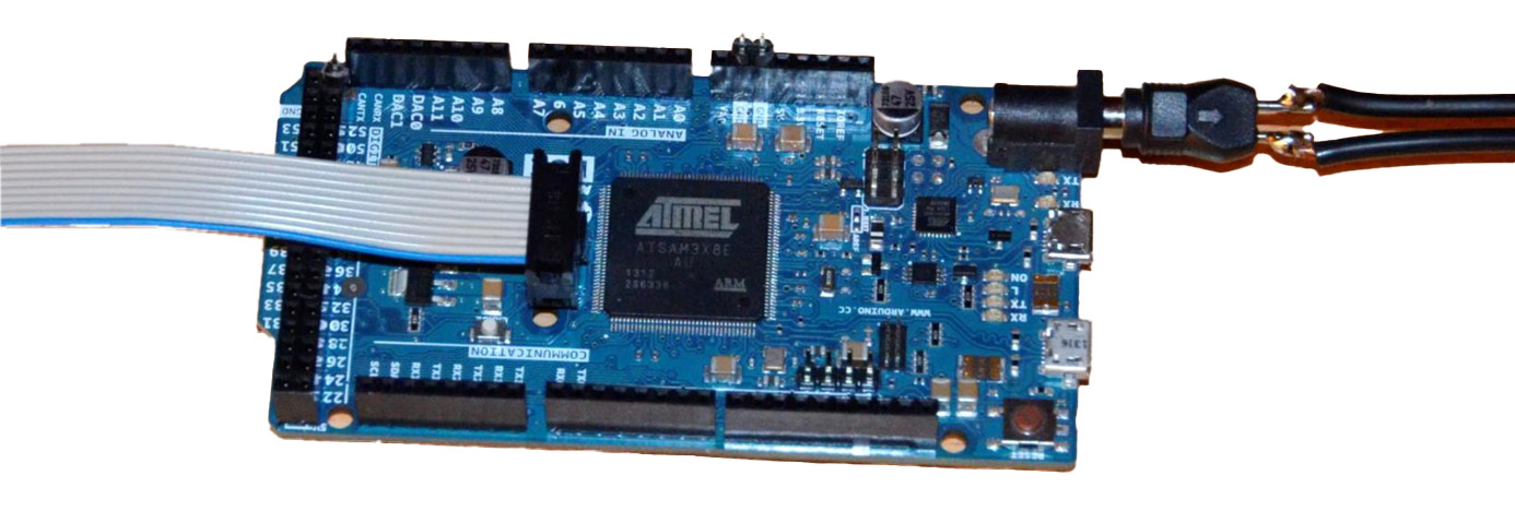
The PCB to be troubleshooted (DUT) is a microcontroller board with two cables connected. The first cable is used for the voltage supply, the second one is used for the connection to a communication partner via a serial interface.
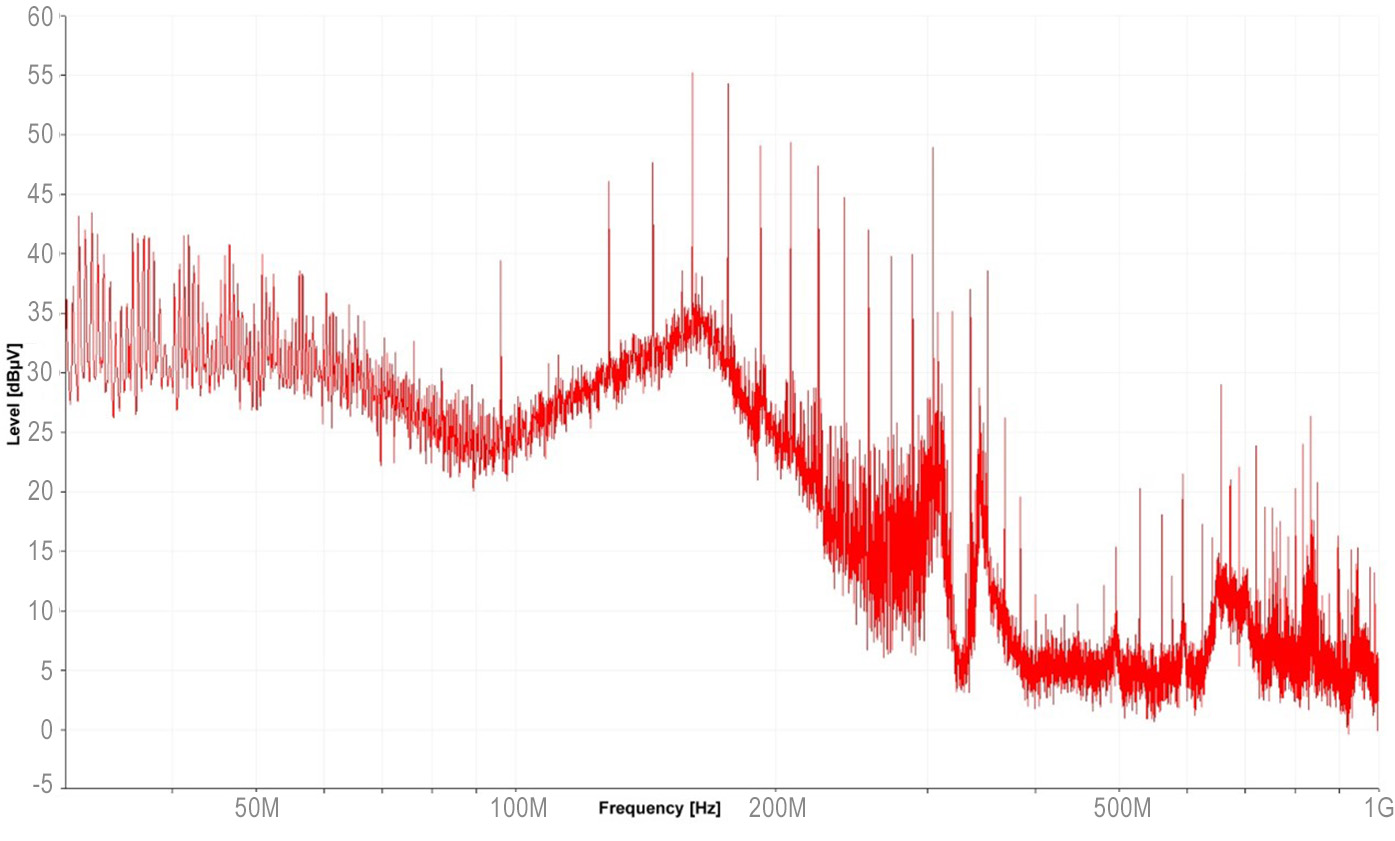
Radiated Emission Spectrum
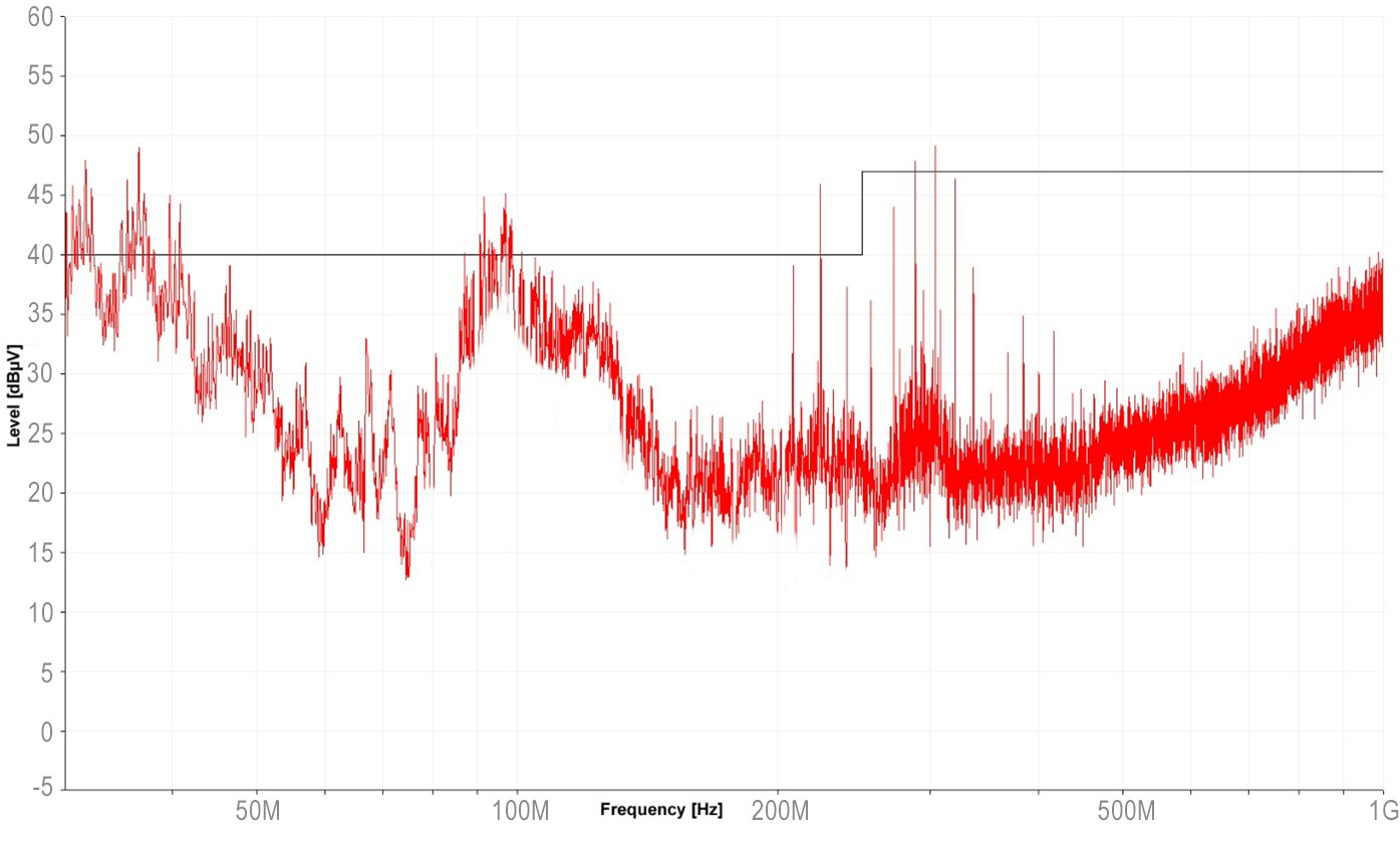
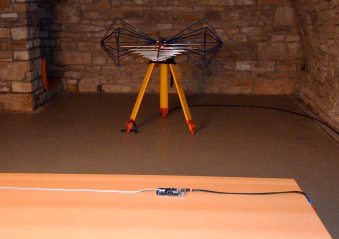
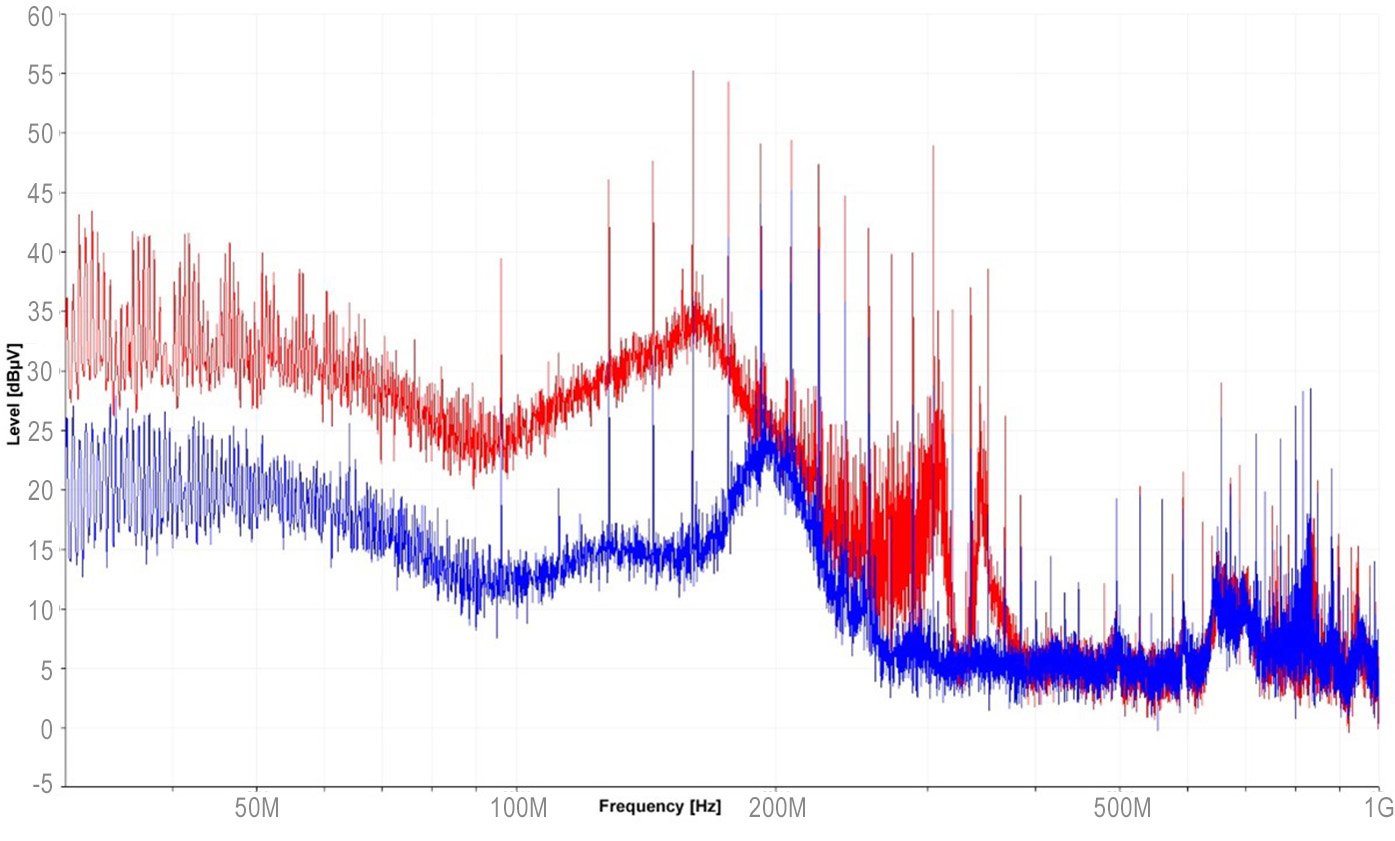
The radiated emission of this board and its cables was measured with an antenna in the far field and has the following spectrum, showing several limit violations.
Step 1: Reproduction
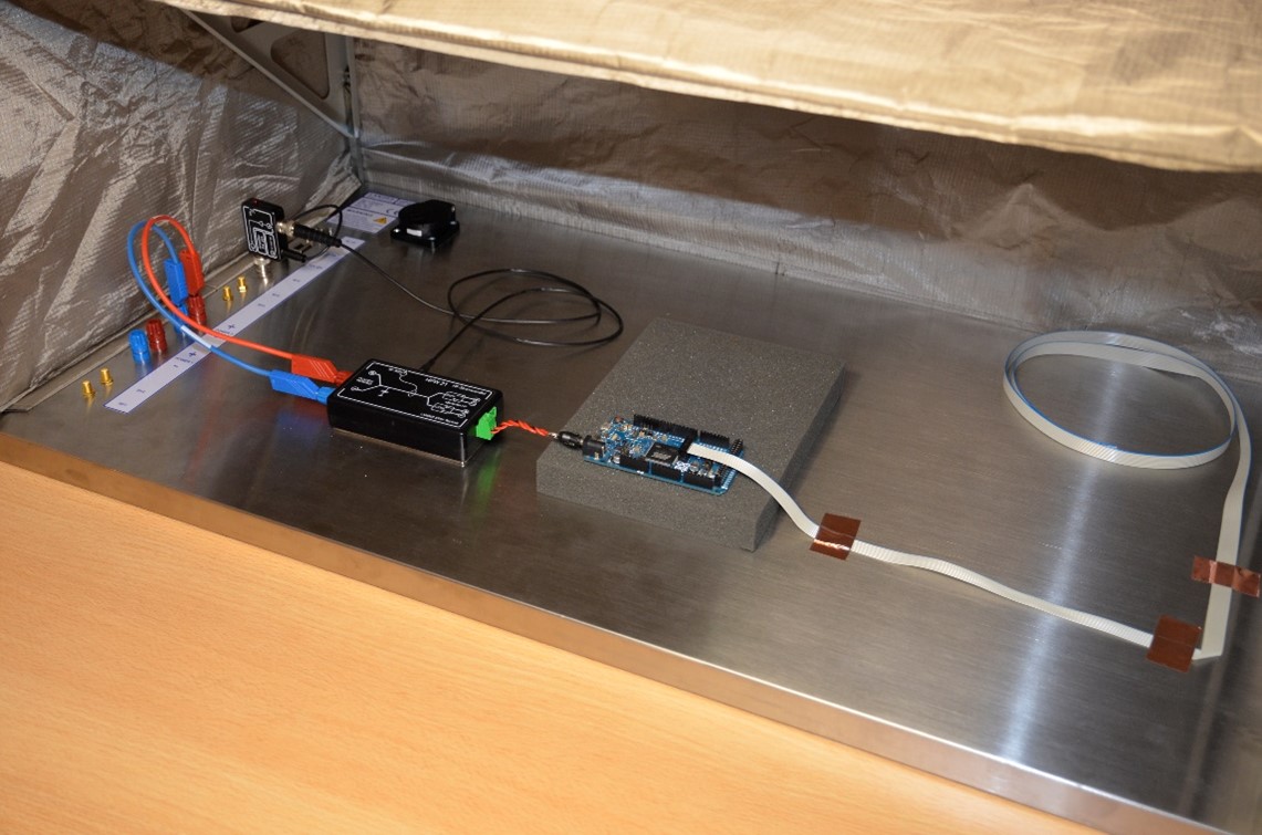
The ESA1 set from Langer EMV-Technik GmbH is used for troubleshooting and can be set up directly at the hardware designer's desk. The circuit board is placed on the base plate of the shielding tent and the DUT is supplied with power via the HFW 21.
The HFW 21 is an RF current transformer. It measures the high-frequency excitation currents from the DUT that cause the antenna, consisting of cables and PCB, to radiate. The measured spectrum is recorded with the tent closed and differs slightly from the emission spectrum of the antenna measurement. The results are proportional to each other.
Step 2: Investigation and Modification
To locate the RF sources on the DUT, near-field probes are used in the open tent. Using an E-field probe, a strong electric RF field can be measured around the coil of the DC-DC converter. The communication cable is placed directly above the coil (Figure 1), coupling disturbances into the cable. The harmonics of the 500 kHz clocked DC/DC converter exceed the limit by 5 dB at around 100 MHz in the antenna measurement (Figure 2), so interference should be reduced by more than 5 dB (ideally 10 dB).
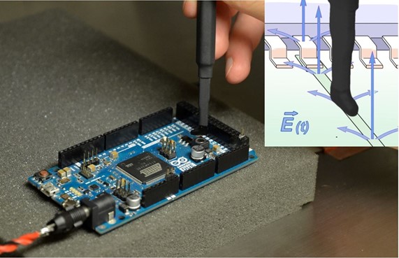
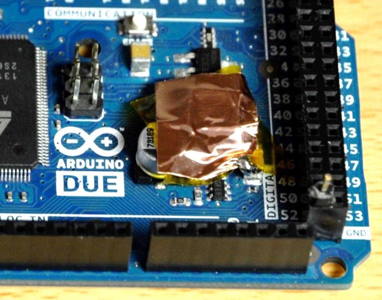
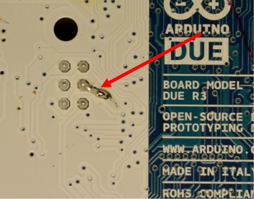
To reduce electric field coupling, a shield is placed over the coil of the DC-DC converter and connected to the DUT ground.
A magnetic field probe identifies the clock line of the serial interface in the ribbon cable as a source of interference (Figure 8). Spikes between 200 MHz and 400 MHz correspond to the antenna measurement frequencies (Figure 2).
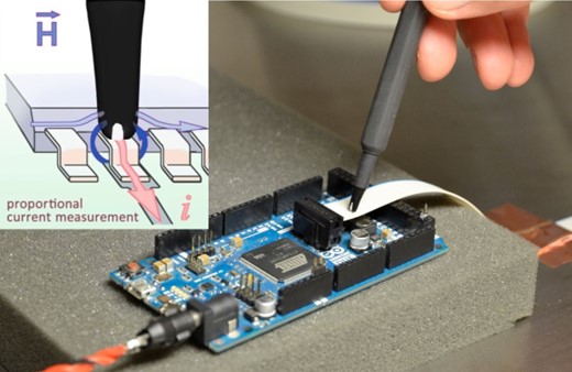
To reduce these spikes, a 47 pF filter capacitor is added to the clock line.
Step 3: Verifying the Effectiveness
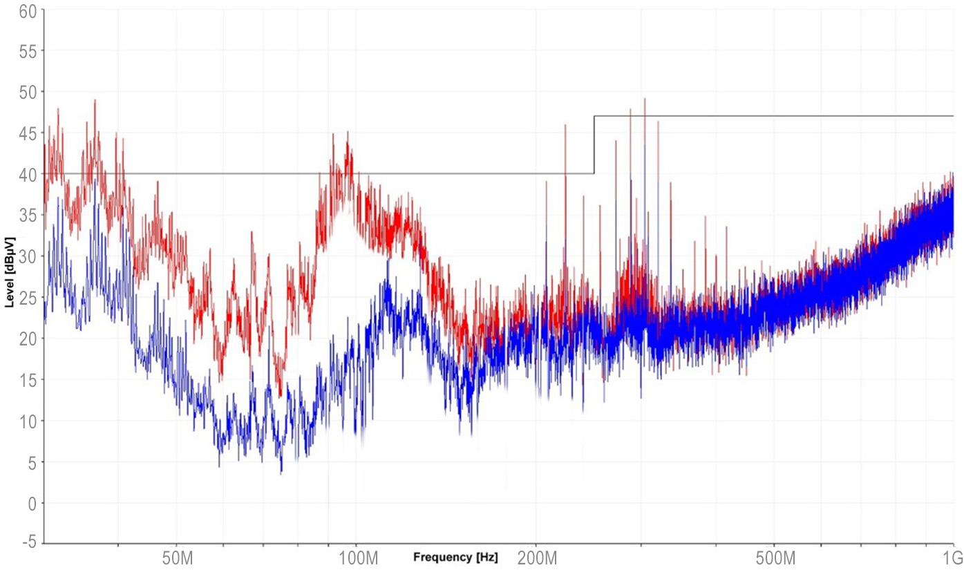
Effectiveness is checked with an HFW 21 measurement in a closed tent. The high-frequency excitation currents in the supply cable were successfully reduced.
Shielding the coil reduces broadband interference at lower frequencies, while the capacitor on the clock line reduces spikes. With these modifications, another antenna measurement can confirm that the limit violations are eliminated.
The EMC problem is fully solved once a production-feasible implementation of these modifications is identified, for example by relocating the coil on the PCB assembly.